
Charging Systems and Electrical Diagnostics
Charging System and Electrical Diagnostics
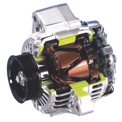
The battery won’t have enough reserve power to restart the engine, so the vehicle will be stranded. Charging output is controlled by a voltage regulator that may be mounted inside or on the back of the alternator (internally regulated, pic A) or somewhere else under the hood (externally regulated).
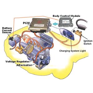
On most newer vehicles the powertrain control module (PCM) regulates charging output. Some also use inputs from the body-control module (BCM, pic B). Many computer-controlled charging systems use pulse width modulation (PWM) to switch the current to the rotor’s field coils on and off. Increasing the duty cycle (on time) of the field coils increases charging output. Amp ratings may range from 80A up to 150 or more. Alternator power ratings can also be given in watts (which is volts times amps). Replacement alternators should have the same power rating (in amps or watts) as the original so the charging system can maintain the same power output.
 One way to minimise the risk of premature failure, and unnecessary warranty returns and comebacks, is to check for excessive resistance
(voltage drops) in the charging circuit.
One way to minimise the risk of premature failure, and unnecessary warranty returns and comebacks, is to check for excessive resistance
(voltage drops) in the charging circuit.Voltage-drop testing - A positive-side voltage-drop test is made by touching the voltmeter’s positive (+) test lead to the ‘B+’ terminal at alternator, and the voltmeter’s negative (-) test lead to the positive (+) battery post (not the terminal clamp). Read the voltage drop with the engine running and the charging system loaded (high beams, high blower and a/c on, etc). The voltage drop should be less than 0.2V if the connections are good. If the reading is higher than 0.2V, inspect and clean all the connections as needed.
On some GM (i.e. Holden) vehicles a voltage drop of up to 0.5V on the positive side may be acceptable. Check service specifications. If you encounter a late-model GM vehicle with a charging output that remains constant at 13.8V and does not change, the voltage regulator is operating in default mode due to an external control problem.
Causes of Alternator Failure
One way to minimise the risk of premature failure, and unnecessary warranty returns and comebacks, is to check for excessive resistance (voltage drops) in the charging circuit.
Voltage-drop testing - A positive-side voltage-drop test is made by touching the voltmeter’s positive (+) test lead to the ‘B+’ terminal at alternator, and the voltmeter’s negative (-) test lead to the positive (+) battery post (not the terminal clamp). Read the voltage drop with the engine running and the charging system loaded (high beams, high blower and a/c on, etc). The voltage drop should be less than 0.2V if the connections are good. If the reading is higher than 0.2V, inspect and clean all the connections as needed.
 On some GM (i.e. Holden) vehicles a voltage drop of up to 0.5V on the positive
side may be acceptable. Check service specifications. If you encounter a late-model
GM vehicle with a charging output that remains constant at 13.8V and does not change,
the voltage regulator is operating in default mode due to an external control problem.
On some GM (i.e. Holden) vehicles a voltage drop of up to 0.5V on the positive
side may be acceptable. Check service specifications. If you encounter a late-model
GM vehicle with a charging output that remains constant at 13.8V and does not change,
the voltage regulator is operating in default mode due to an external control problem. 